For the basic Robot(level-1)
First of all lets understand the DC motors.
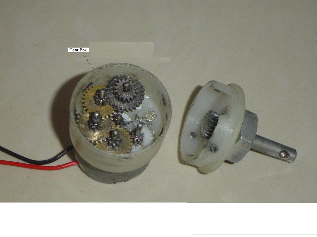
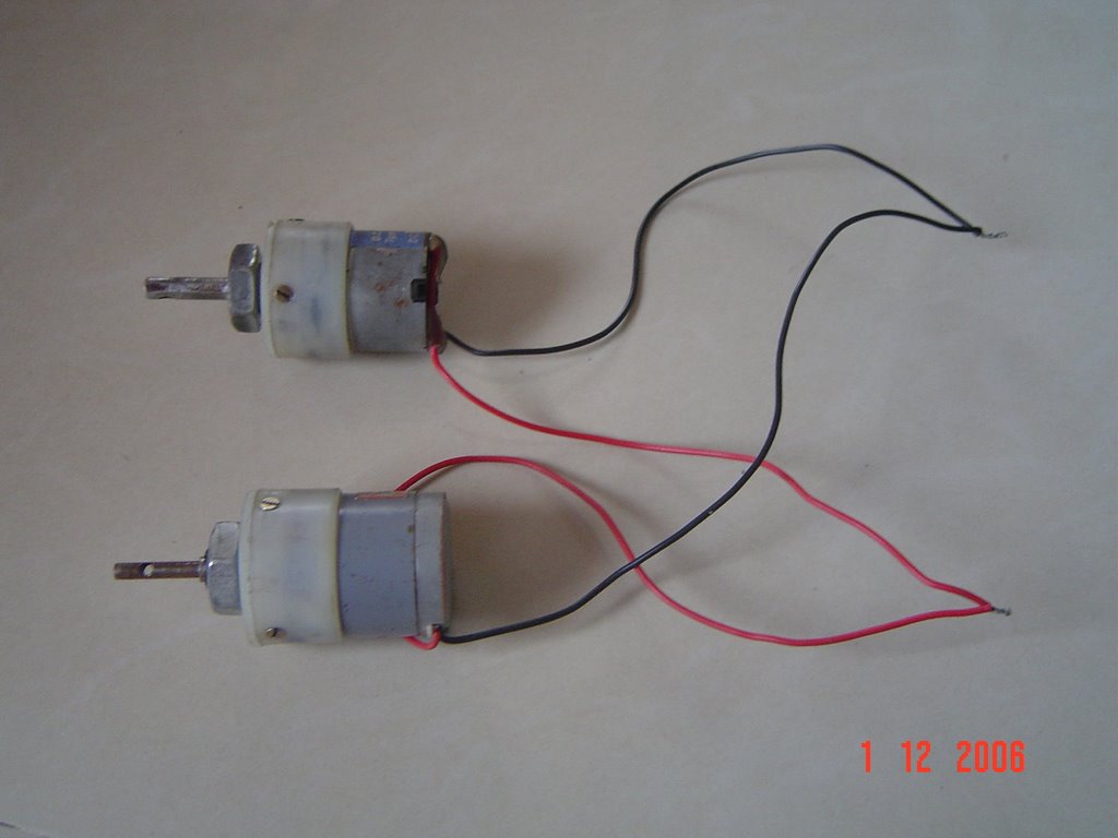
- DC motors are geared motors. These contain a Gear box at the top and the silver coloured part in the picture is the main motor that drives the axle.
as u can see in the first fig. to the extreme left . there are various gears in it. these are step gears which reduce the high r.p.m to the desired r.p.m
The main motor gives around 2000 r.p.m whereas the gear box reduces it to the desired r.p.m { 15 r.p.m in this case } - Now, one thing to keep in mind that the Torque is inversly proportional to the speed.
TORQUE = k/ SPEED
where k is a constant. - In a laymans language Torque is the power given by the motor to overcome the obstacle.
If you want high speed then u have to compromise with the Torque and if u want high torque than compromise with the speed. - Generally for normal robotics competition {level 1} one should go for 300 r.p.m motors as they provide you the combination of torque as well as speed.
I hope you guys got the concept of torque and speed by now..
DRIVE FOR ROBOT:

- You can use any material for the body of your robo. It can be either wood, M.S plate. Aluminium, etc. depending upon the weight requirements
- Generally the cars on our roads are rear wheel drive. But for the competitions this won’t serve the purpose.Let us see the disadvantages In the fig the one with dark rear wheel is rear wheel drive while the other is four wheel drive.{ ie. All the four wheels powered by motors }
- How do the robo car overcome an obstacle ? When a car is moving the wheel rotates in clockwise direction while moving forward. and hence the friction force acts in anticlockwise direction. This makes the car move forward. Similarly it overcomes an obstacle. Now if the car is climbing an inclined plane. Then in case of rear wheel drive there will be no friction force on the front wheels because they r not powered and hence unable to generate a reaction. Due to this the car will topple upside down.
\ - Same is the case while clearing an obstacle in rear wheel drive and it won’t be able to clear it.
- But in four wheel drive each wheel generates a reaction . and there acts a friction force. Hence it is able to clear all the obstacles as well as climb the inclination with higher degree than that of rear wheel drive car.
- The very fact that Centre of gravity plays an important role .
The C.G ON A FOR WHEEL DRIVE ACTS ON THE CENTRE OF THE BODY.
ON REAR WHEEL DRIVE IT ACTS BETWEEN THE TWO MOTORS.
by adding some dead weight on the front side and shifting the C.G somewhere in between can serve the purpose in rear wheel drive.

- The very common example can be a normal four wheeler and a HUMMER. Hummer is a four wheel drive vehicle hence can even climb uneven terrains..
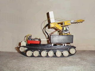
we can also use a belt as used in tanks on wheels as it can be seen in the pic. above. but again this har advantage on the sand. what is observed during robotics competitions is that the belt comes off while overcoming an obstacle or by excessive jerks. hence it is advisable to avoid such method. - For normal competitions in robotics we need to clear a track in minimum possible time or win a knockout race. So we need speed as well as enough torque to overcome all obstacles. As I wrote on my last post a 300 r.p.m motor would serve both purpose and also it should be a four wheel drive.
CIRCUITRY:

- The circuitry of a normal robotic car. This circuitry will enable the robo to move forward, backward, left and right. Now starting with circuitry we need 2 two way switches. These switches conduct in both directions hence the name two way switches. Firstly we sort the terminals
1 and 6 { first switch}
2 and 5 { “ }
1’ and 6’ { second switch}
2’ and 5’ { “ } T - hen we choose the terminals of first switch ie. 5 as positive or 6 as positive . either way one wants to, can do so. But one thing has to be kept in mind that if 5 is positive in 1st switch then 5’ should be the + ve terminal of 2nd switch. The same convention for negative terminal. POWER SUPPLY
- Terminals 3,4 from 1st switch and terminals 3’, 4’ from 2nd switch are the power supply terminals. In this too we have to use the same convention like the +ve and –ve terminals of either switches. If we take 3 as +ve than we have to take 3’ as +ve and give this combined combination to the powe supply as +ve. The same case for negative ie. Combination of 4 and 4’ for negative. Or the reverse can also be done.
- The terminals 3 and3’ are sorted with the help of wires and similarly we sort the terminals 4 and 4’. The output single wire from 3 and 3’ combination will be given to + ve of the power supply and the output single wire from the combination of 4 and 4’ will be given to the – ve of the power supply.
- Power supply can be an adaptor or an eliminator of 12 volts. This is the connection we make in switch. Now how to proceed with combining this connection with motors. MOTOR CONNECTION We will call the top and bottom motors on left hand side the left pair and The top an bottom motors on right side the right pair The above picture shows the left pair .
- similarly we have to connect the right pair. LEFT PAIR MOTORS We will bring together the positive of both the top and bottom motor on left hand side and sort them . similarly we will sort the negative of both the motors of the left pair. RIGHT PAIR MOTORS Now as we did in the left pair we will sort the +ve wire of both motors together and sort the –ve of the motors .
- So in all we get 4 output wires from the motor connection . 2 from left pair and 2 from right pair.
- COMBINING THE SWITCH AND MOTOR CIRCUIT Now to connect the switch to motors we have to choose four output from the switch connection as we have four output from the motor connection.
- We will consider the terminal 5 and 6 from the first switch and 5’ and 6’ from second switch. Considering the terminal 5 from first switch positive terminal 5’ will be positive from second switch. Similarly 6 and 6’ are considered as negative.
- Now the connection goes this way positive wire combination from left pair motors will be connected to point 5 negative wire combination from left pair motors will be connected to point 6 positive wire combination from right pair will be connected to point 5’ negative wire combination from right pair will be connected to point 6’ these connections are made with the help of intermediate wires called the rainbow wires.
- I suppose….. these are a bunch of thin wires used for internal circuitry. If suppose u connect positive wire from left hand pair from motors to red wire then the other end of red wire will be connected to point 5.
- Similarly for all connections. The length of the intermediate wire depends on the user. Normally we take 8 to 9 meters. That will be the range of your robo.
No comments:
Post a Comment